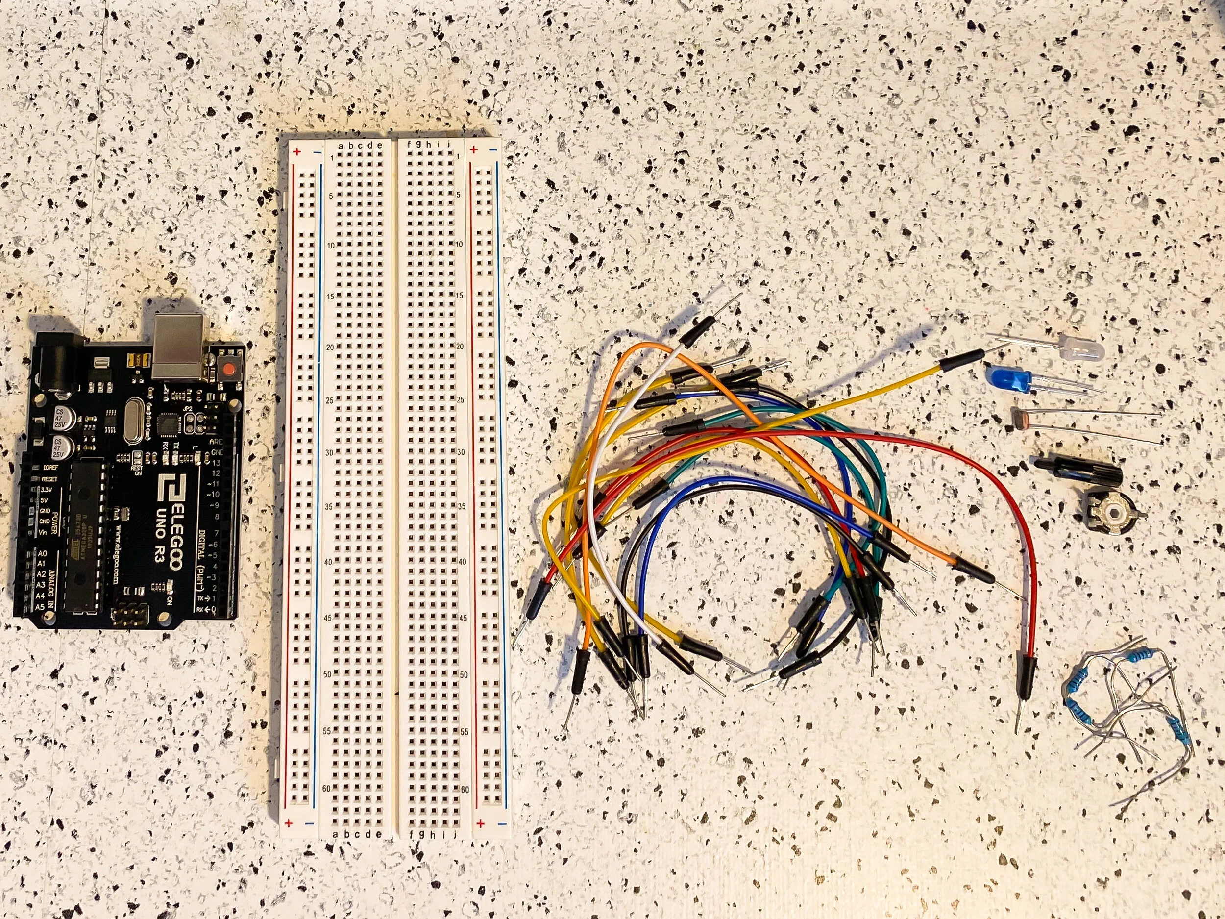
In this lab, we explore analog input and output using variable resistors. We will learn to read sensor values to the serial monitor and utilize pulse width modulation (PWM) to affect outputs.
All of the necessary supplies for this week’s lab
Analog Input and Output
To begin, I started setting up my circuit by connecting the ground and power jumper wires from the Arduino to the breadboard. I have placed my white LED and blue LED, as well as two 220 Ohm resistors for each. I connected both with jumper wires to the digital PWM output pins on the Arduino.
Closer view of my circuit
Initial setup of the circuit with potentiometer and LDR
I added the potentiometer and light-dependent resistor (LDR) next, as well as a 10k resistor and the necessary jumper wires. I then connected them to the analog in pins on the Arduino.
The next step was to write my code. This would require analogRead() and analogWrite() functions to read the value from the potentiometer or LDR, map the values, then write them to an output value that the LEDs understand and therefore dim. This code can be viewed below.
When I ran my code, nothing happened. That’s always a good sign!
To start troubleshooting, I double-checked my code and and touched and moved all of the wires and resistors on my breadboard. When that didn’t work, I changed around my circuit a little bit. I realized that I had put my LED anodes in the wrong spots, and also moved my LDR and connections. After that, this was the result.
As you can see, something was off, and I tried moving things around to get a new result. I knew that this was an issue with the PWM and perhaps the values it was sending to output. I changed the code and separated the blue LED from white so that one was changed by the potentiometer and one by the LDR, which I think is what I was supposed to do in the first place. This code is below.
After this change as well as a change in the value range for the LDR mapping, it appeared to work! The change in the white LED from the LDR is less noticeable than the blue led, but you should be able to see a slight change in the video.
Lastly the schematic for this circuit can be viewed below.
Schematic diagram for the circuit


