For this lab, we will explore analog output through frequency modulation. We will practice how to connect analog sensors to the Arduino, and connect this input to sound through a piezo buzzer.
All of the necessary supplies, such as jumper wires, LDRs, and the piezo buzzer
Tone Output
Our first step in this lab will be to make a simple circuit to test the piezo buzzer’s output sound. This requires a very basic circuit and a couple new functions to code, such as tone(). I set up the circuit by making sure the ground and power rails were connected and plugged everything into the Arduino.
The code for this portion as well as the schematic is below.
Simple circuit with piezo buzzer (supplies for later pictured to the left of the circuit)
Schematic for tone output circuit
Now, we test it out! I tried to stick with frequencies that wouldn’t pain me or anyone listening, and made it a repetitive sound. It’s not bad!
Analog Sensor Input
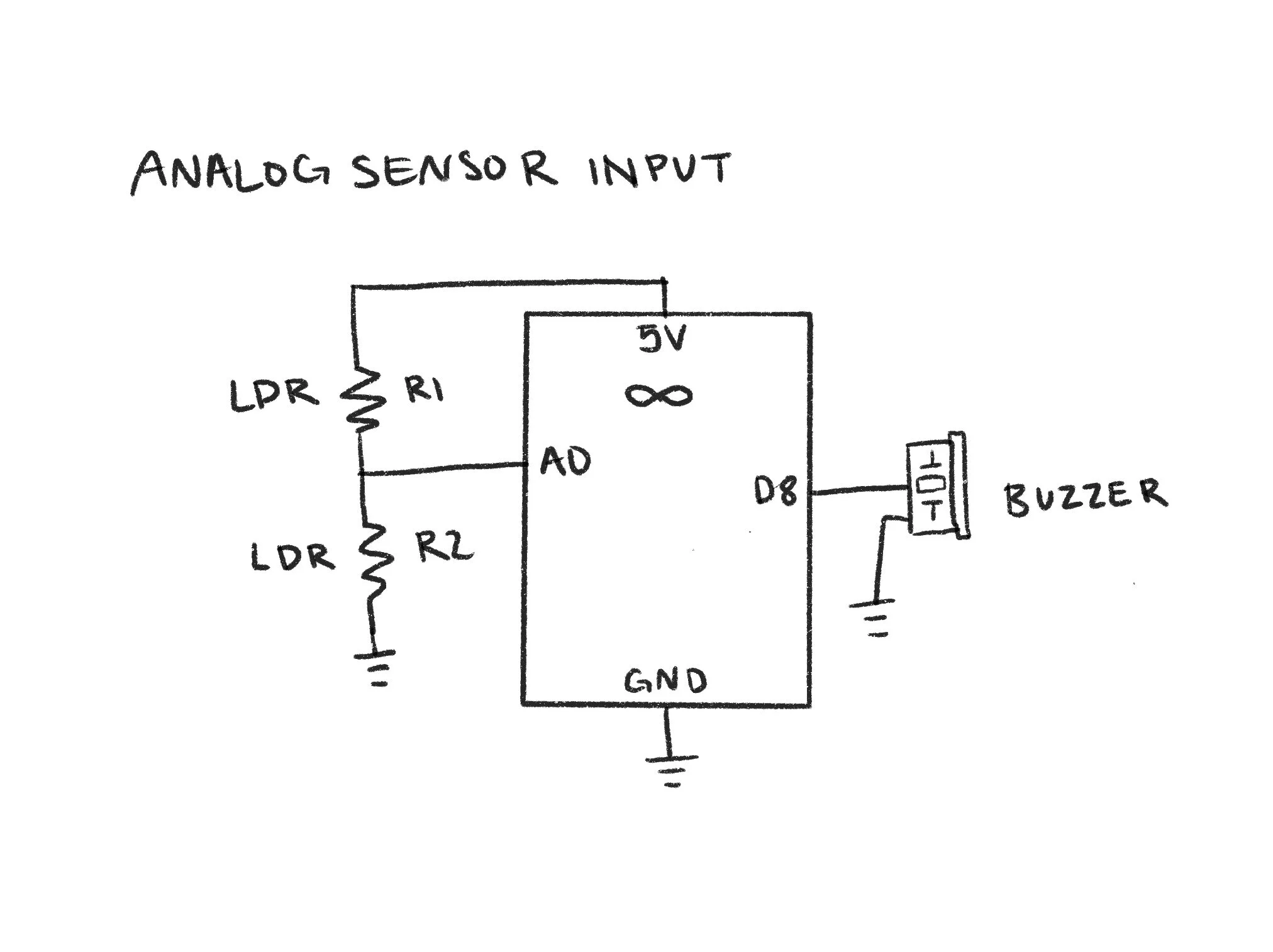
Next, it was time to try out adding an analog sensor input to change the sound from the piezo buzzer. To do this, I added two light-dependent resistors to my circuit, ensuring they were connected and grounded properly.
Circuit with LDRs as an analog sensor input and piezo buzzer for the output
In terms of code, this would look very similar to our previous lab in which we need to map the values the LDRs read and then write that as a frequency for the piezo buzzer to send back. This portion was also fairly straightforward, and the code and schematic are below.
Schematic for analog sensor input circuit
Now, we just make sure it works!
Push-button Piano
Now begins the fun. We will be replacing our analog sensor input (LDRs) for buttons. When the buttons are pressed, they will play different notes. To do this, I connected three buttons and jumper wires to my breadboard, making sure each had a power and ground connection.
Circuit with piezo buzzer and three push-buttons as inputs
I utilized the digitalRead function to determine if the buttons were being pressed, and the digitalWrite function to make the code realize something should happen if the read is a LOW value, in this case, play a note. I also used INPUT_PULLUP with my buttons to create built-in resistors. I then used three different C note scales to ensure a clear difference between the three buttons, and it works!
Schematic for bush-button piano circuit
Custom Musical Instrument
Time for even more fun. I have free reign to do whatever I want for this part, so I decided to make a paper piano with a twist. To begin, I set up my circuit to organize the soon-to-be-chaos. I created spots for seven keys, each connected to a different digital pin.
Start of the circuit with digital pins connecting to what will be my physical switches
Thin cardboard used for piano “keys”
I then started cutting out what would be my keys. The idea is to create a physical switch within each key, so when pressed down, the switch would close and then return what I tell the code to do.
I spent a lot of time connecting the wires to the cardboard keys and taping things down with copper tape, so that when folded, the conductive tape would connect and close the circuit.
As you can see in the photo on the right, I started with just the tape, but you will soon see that this was not enough.
Physical switch “key”
Key switches laid out with added foil
The tape was rather flimsy and the wires had a mind of their own. I had to do a lot of trouble-shooting at this stage, adding foil, adding tape, retrying.
I also did a little painting with watercolor to create some abstract flowers to connect the keys to so the piano would look nicer.
I worked on the code portion next, which was very similar to the previous section. I added variables for each pin and corresponding key, but this time the note played would relay to a standard piano scale, starting with C and going to B. However, this is where I added my twist. I used portions of code found on Github to play the chorus of “Never Gonna Give You Up” by Rick Astley. This would occur when the D key is pressed, as D is the first note of the chorus.
Schematic for paper piano circuit
I have successfully rick-rolled my peers with an Arduino, and I love it!


