
In this week’s lab, we are dipping our toes in the water of basic electronics and circuits by creating an LED circuit

Breadboard with only the jumper wire and and voltage regulating circuit connected
To begin, I have connected my breadboard voltage regulating circuit board and set the jumpers to 5V, as well as connecting to a 9V battery. On the positive side, I have connected a jumper wire, then added my LED, followed by a 220 Ohm resistor to the negative side. I chose to lay this circuit out on my breadboard from left to right so as to make it easy to understand and easy to follow the schematic.

LED light powered on with 220 Ohm resistor
The second picture, to the right, is using a 1K Ohm resistor, which limits the voltage to the LED and therefore make the light dimmer. Although slight, the change is existent.

Full circuit made with jumper wires connecting to LED and then a 220 Ohm resistor
When the switch is turned on, the LED lights up. The first picture, on the left, is the light emitted with the 220 Ohm resistor.

LED light powered on with 1K Ohm resistor

Circuit with a light-dependent resistor rather than a fixed resistor
After working with the fixed resistors, I swapped them for a light-dependent resistor (LDR), which is pictured above. This time, when switched on, you can see in the photo to the right the amount of light emitted by the LED when there is significant overhead light shining on the LDR.

LED light powered on with the LDR covered

LED light powered on with the LDR uncovered
I then adjusted the light to the LDR by covering it with my finger, and as pictured to the left, the LED was noticeably more dim.
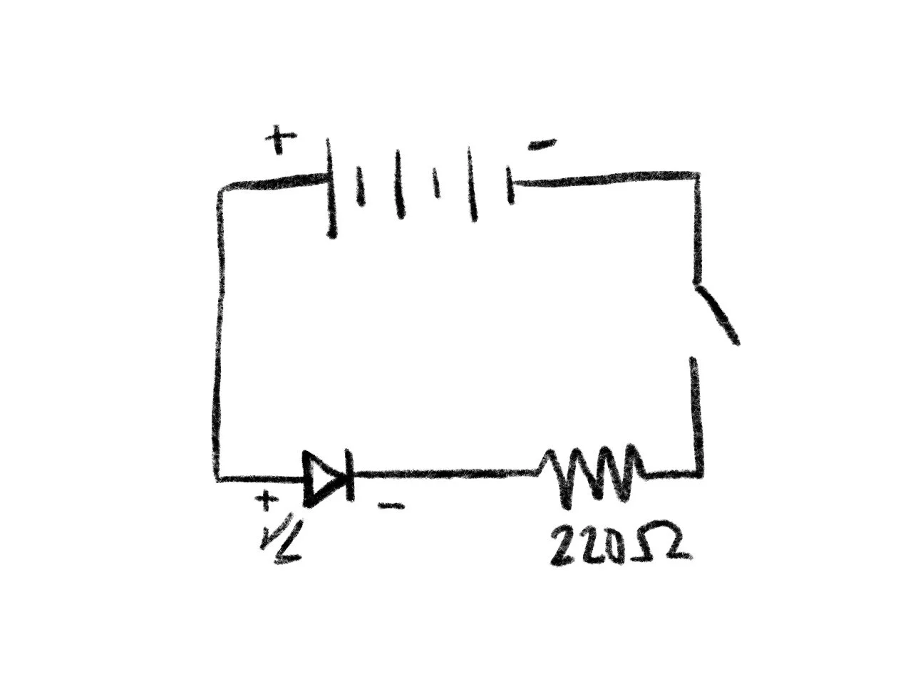
Schematic of basic LED circuit with a 220 Ohm resistor
Lastly, the schematic for the basic LED circuit is pictured above. This depicts the power source at the top, with the positive side going to the LED, then the 220 Ohm resistor and switch to show the ability to open and close the circuit, or turn the light on and off with a button.