In this lab, we will continue to grow upon basic electronics and simple circuits, as well as calculating resistor values and using Ohm’s law.
All of the necessary supplies for this week’s lab
LEDs in Series and Parallel
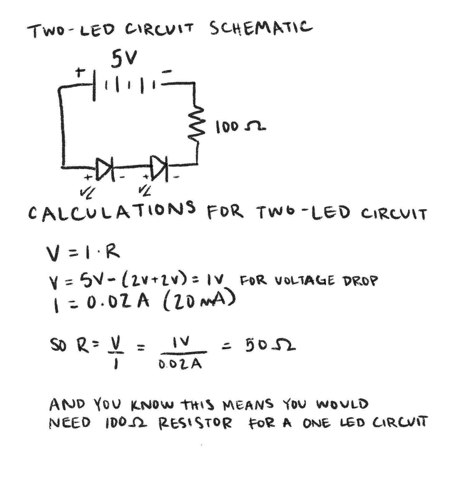
Calculation and schematic for two-LED circuit
To begin, I have calculated the amount of current running through our basic LED circuit from the last lab if I replace the resistor with one that is 10k Ohm.
If I add a second LED to the series circuit, I now need to calculate a new value required for the resistor to maintain a 20 mA current across both. Pictured to the left is this calculation and schematic, and below is a photo of the circuit itself.
Series circuit with two LEDs, the first being slightly brighter than the second
Next, I added a third LED to this series. In the picture, although hard to tell, you can see that the second LED is far dimmer than the first, and the third does not light up at all. This is because our LEDs have a voltage drop of 2V, and since we are using only 5V, this does not leave enough voltage in this circuit to power the third LED.
Series circuit with three LEDs, the first being brighter, and the third not lighting up at all.
Parallel circuit with three LEDs, which are not powered on in this photo
I then rearranged my circuit into a parallel circuit with the three LEDs. I used 100 Ohm resistors for each LED, but I realized after photographing this that I could use a much higher Ohm resistor. I did not attach the photo of this circuit when on, because the LEDs were so bright that it made the coloring difficult to see in a photo.
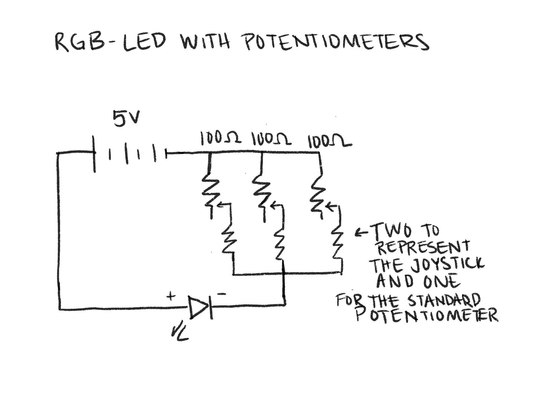
Next, I changed out all three of the LEDs with an RGB-LED, and attached a joystick and potentiometer. The joystick will control two of the colors while the potentiometer will control the third. This is where I ran into some problems. For some reason, the joystick was successfully controlling the red and green LED, but the blue was not turned on, and twisting the potentiometer was fruitless.
RGB-LED with only the green and red LED functioning using the potentiometer
RGB-LED working partially with the potentiometer after holding the jumper cables in particular spots
I had to do a lot of trouble-shooting, expecting that I was simply doing something wrong, but I came to the conclusion that the potentiometer was not working properly. When I fiddled with the jumper wires, it would somewhat bring the blue LED on, but it was inconsistent. I then switched out the potentiometer for a regular old jumper cable, and BAM! It worked!
Schematic for RGB-LED circuit with potentiometers
Resistors in Series
Schematic and calculations for a circuit in series
To confirm these calculations, I modeled the circuit in PhET. These were confirmed by checking the voltage of the second resistor, which matches that of my second voltage drop calculation.
Now moving on, I have calculated the overall resistance, overall current, and voltage drop across resistors of the given series example.
A PhET model of a circuit with three resistors and 5V, measuring the voltage at the second resistor
Resistors in Parallel
Schematics and calculations for a circuit in parallel
I confirmed these calculations in PhET once again. You can see that my calculation for V2 matched the voltage on the PhET circuit.
I then did the same with two more parallel circuits, which have different characteristics from series circuits.
A PhET model of a parallel circuit with three resistors and 5V, measuring the voltage at the second resistor
Arduino Installation
Lastly, I prepared for next week by setting up and installing the Arduino environment. That info is pictured below.


