Serial Game or Audio Controller

In this lab, we will create an interactive application in P5.JS and use serial communication to send values between the Arduino and our application

Static Scene.png

To start, I had to get my grounding in p5.js

Luckily, this felt very similar to using the draw function in Python as well as some other coding experience I have, so it didn’t take long to get a few things figured out.

Part 1

The first step would be to create a static scene in the p5 web editor. I started by adding a few circles, playing with the position, color, and transparency, so that when overlapped, there would be a noticeable change.

Progress 1.png

I then added a lot more, and changed the color and position of each. I liked the organic and unexpected nature of where the circles ended up. I was going to variate the sizes, but I actually liked keeping it just one size.

I then decided I was happy with my static sketch, which can be viewed below. The link to the code in the web editor can be found here.

Next, I would make this sketch interactive. I knew I wanted to use the mouse to change what happens in the scene, so I used the idea from our example sketch with the map() function to map the location of the mouse as x and y values and then add that to the x and y values of each of the circles.

Now, when moused over the sketch, the cluster would move with the mouse, albeit slighter movements so as to keep them on the screen.

I then added an if() function with mouseIsPressed, so that, as could be assumed, something would change if the mouse is being pressed. I then changed the size the circles, so they get bigger when clicking the mouse. I left the mouse movement as well, so it will always move, big or small.

The sketch can be viewed below, and the link to the web editor for this can be found here.

Build a Musical Instrument

For this lab, we will explore analog output through frequency modulation. We will practice how to connect analog sensors to the Arduino, and connect this input to sound through a piezo buzzer.

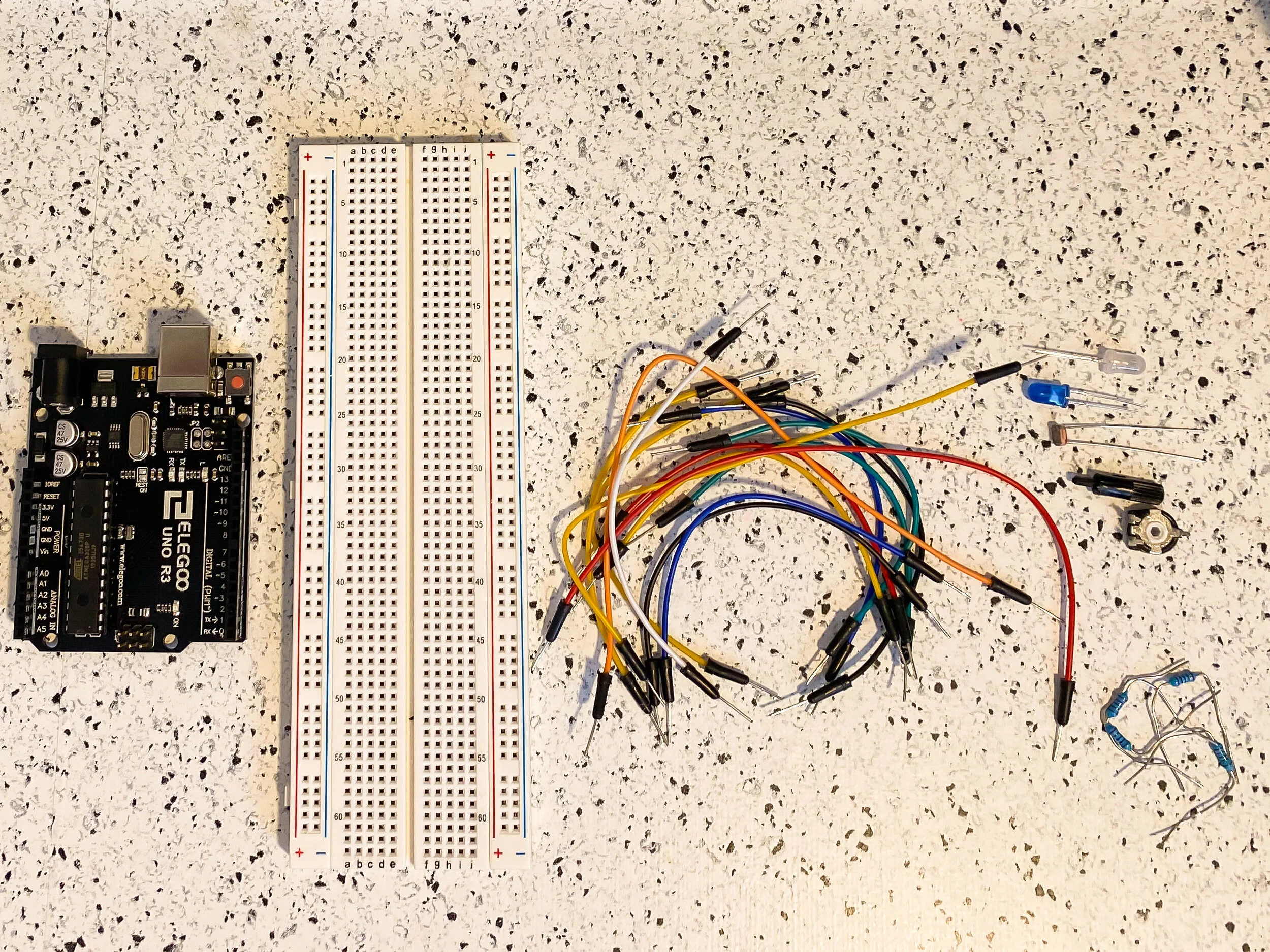
All of the necessary supplies, such as jumper wires, LDRs, and the piezo buzzer

All of the necessary supplies, such as jumper wires, LDRs, and the piezo buzzer

Tone Output

Our first step in this lab will be to make a simple circuit to test the piezo buzzer’s output sound. This requires a very basic circuit and a couple new functions to code, such as tone(). I set up the circuit by making sure the ground and power rails were connected and plugged everything into the Arduino.

The code for this portion as well as the schematic is below.

Simple circuit with piezo buzzer (supplies for later pictured to the left of the circuit)

Simple circuit with piezo buzzer (supplies for later pictured to the left of the circuit)

Schematic for tone output circuit

Schematic for tone output circuit

Now, we test it out! I tried to stick with frequencies that wouldn’t pain me or anyone listening, and made it a repetitive sound. It’s not bad!

Analog Sensor Input

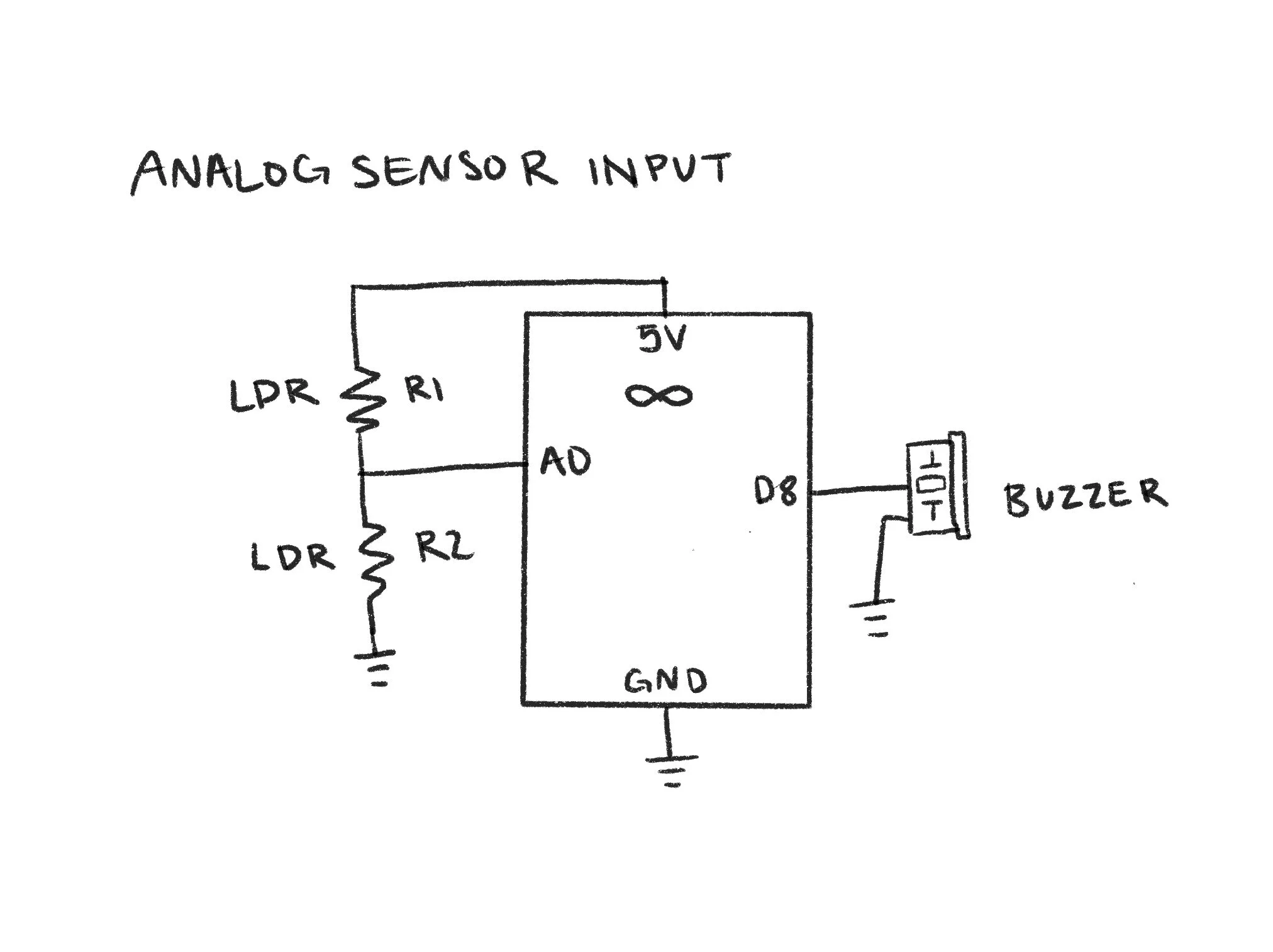
Next, it was time to try out adding an analog sensor input to change the sound from the piezo buzzer. To do this, I added two light-dependent resistors to my circuit, ensuring they were connected and grounded properly.

Circuit with LDRs as an analog sensor input and piezo buzzer for the output

Circuit with LDRs as an analog sensor input and piezo buzzer for the output

In terms of code, this would look very similar to our previous lab in which we need to map the values the LDRs read and then write that as a frequency for the piezo buzzer to send back. This portion was also fairly straightforward, and the code and schematic are below.

Schematic for analog sensor input circuit

Schematic for analog sensor input circuit

Now, we just make sure it works!

Push-button Piano

Now begins the fun. We will be replacing our analog sensor input (LDRs) for buttons. When the buttons are pressed, they will play different notes. To do this, I connected three buttons and jumper wires to my breadboard, making sure each had a power and ground connection.

Circuit with piezo buzzer and three push-buttons as inputs

Circuit with piezo buzzer and three push-buttons as inputs

I utilized the digitalRead function to determine if the buttons were being pressed, and the digitalWrite function to make the code realize something should happen if the read is a LOW value, in this case, play a note. I also used INPUT_PULLUP with my buttons to create built-in resistors. I then used three different C note scales to ensure a clear difference between the three buttons, and it works!

Schematic for bush-button piano circuit

Schematic for bush-button piano circuit

Custom Musical Instrument

Time for even more fun. I have free reign to do whatever I want for this part, so I decided to make a paper piano with a twist. To begin, I set up my circuit to organize the soon-to-be-chaos. I created spots for seven keys, each connected to a different digital pin.

Start of the circuit with digital pins connecting to what will be my physical switches

Start of the circuit with digital pins connecting to what will be my physical switches

Thin cardboard used for piano “keys”

Thin cardboard used for piano “keys”

I then started cutting out what would be my keys. The idea is to create a physical switch within each key, so when pressed down, the switch would close and then return what I tell the code to do.

I spent a lot of time connecting the wires to the cardboard keys and taping things down with copper tape, so that when folded, the conductive tape would connect and close the circuit.

As you can see in the photo on the right, I started with just the tape, but you will soon see that this was not enough.

Physical switch “key”

Physical switch “key”

Key switches laid out with added foil

Key switches laid out with added foil

The tape was rather flimsy and the wires had a mind of their own. I had to do a lot of trouble-shooting at this stage, adding foil, adding tape, retrying.

I also did a little painting with watercolor to create some abstract flowers to connect the keys to so the piano would look nicer.

I worked on the code portion next, which was very similar to the previous section. I added variables for each pin and corresponding key, but this time the note played would relay to a standard piano scale, starting with C and going to B. However, this is where I added my twist. I used portions of code found on Github to play the chorus of “Never Gonna Give You Up” by Rick Astley. This would occur when the D key is pressed, as D is the first note of the chorus.

Schematic for paper piano circuit

Schematic for paper piano circuit

I have successfully rick-rolled my peers with an Arduino, and I love it!

Arduino and Analog I/O

In this lab, we explore analog input and output using variable resistors. We will learn to read sensor values to the serial monitor and utilize pulse width modulation (PWM) to affect outputs.

All of the necessary supplies for this week’s lab

All of the necessary supplies for this week’s lab

Analog Input and Output

To begin, I started setting up my circuit by connecting the ground and power jumper wires from the Arduino to the breadboard. I have placed my white LED and blue LED, as well as two 220 Ohm resistors for each. I connected both with jumper wires to the digital PWM output pins on the Arduino.

Closer view of my circuit

Closer view of my circuit

Initial setup of the circuit with potentiometer and LDR

Initial setup of the circuit with potentiometer and LDR

I added the potentiometer and light-dependent resistor (LDR) next, as well as a 10k resistor and the necessary jumper wires. I then connected them to the analog in pins on the Arduino.

The next step was to write my code. This would require analogRead() and analogWrite() functions to read the value from the potentiometer or LDR, map the values, then write them to an output value that the LEDs understand and therefore dim. This code can be viewed below.

When I ran my code, nothing happened. That’s always a good sign!

To start troubleshooting, I double-checked my code and and touched and moved all of the wires and resistors on my breadboard. When that didn’t work, I changed around my circuit a little bit. I realized that I had put my LED anodes in the wrong spots, and also moved my LDR and connections. After that, this was the result.

As you can see, something was off, and I tried moving things around to get a new result. I knew that this was an issue with the PWM and perhaps the values it was sending to output. I changed the code and separated the blue LED from white so that one was changed by the potentiometer and one by the LDR, which I think is what I was supposed to do in the first place. This code is below.

After this change as well as a change in the value range for the LDR mapping, it appeared to work! The change in the white LED from the LDR is less noticeable than the blue led, but you should be able to see a slight change in the video.

Lastly the schematic for this circuit can be viewed below.

Schematic diagram for the circuit

Schematic diagram for the circuit

Arduino and Digital I/O

In this lab, we will learn about the Arduino prototyping environment and explore how to use the digital inputs and outputs of our microcontroller. We will integrate these into a project by building a custom switch and enclosure.
Overview of pull up/pull down circuit for the firs part of this lab

Overview of pull up/pull down circuit for the firs part of this lab

Digital I/O circuit

To begin, we worked through creating a pull-up and pull-down resistor for digital input switches that then control digital outputs via LEDs. This code can be viewed below.

For some reason, this wasn’t working. I double checked my code, checked all of my resistors, replaced my switches with jumper cables, and nothing. I straightened out the pins of the switches to better fit in the breadboard, still nothing. This had just worked the other day, so why not now? I took a little break because I was frustrated and decided to come back to it.

Top switch with straight pins, bottom with still-bent pins

Top switch with straight pins, bottom with still-bent pins

Breadboard with all wires connected, but still not responding

Breadboard with all wires connected, but still not responding

Schematic for digital input/output switches with Arduino

Schematic for digital input/output switches with Arduino

DIY Switch

After working with this digital input and output, I then swapped out the buttons for a physical switch. I changed around my circuit and moved it to the mini breadboard to fit into a smaller space as well as ensuring each LED is independent from each other as my switch will require a piece of conductive copper tape to touch and therefore light each one separately.

My plan for this switch will be a piece of cardboard that, when turned in the direction of each LED, will light the corresponding LED as a sort of indicator. I connected copper tape to jumper wires and cardboard to achieve this.

Carboard with wires attached to copper tape

Carboard with wires attached to copper tape

Circuit created on mini breadboard attached to Arduino

Circuit created on mini breadboard attached to Arduino

I once again ran into troubles with this part, as I had to reorient myself with the layout of the mini breadboard. I double-checked my code and realized that this would be done incredibly simply with strictly analog input, which should make the digital portion easy. The code can be viewed below.

Assembled DIY switch

Assembled DIY switch

Creative Enclosure

For this portion, I worked on turning my DIY switch into a type of enclosure. My first step was to punch through the LEDs. This required attaching the LED leads to female jumper wires and securing with electrical tape to add length.

The front with LEDs punched through

The front with LEDs punched through

The back wiring of my soon-to-be-enclosure

The back wiring of my soon-to-be-enclosure

I made sure I knew which wire went to which lead and which thing and then organized the back by securing with electrical tape. Things were beginning to shape up.

After I got everything secured and attached to the breadboard and Arduino again, I was able to close the other ends of the box. I added the phrase “How do I feel today?” so that this could be a visual indicator of my daily mood. The finished enclosure is pictured below.

Finished enclosure to represent my mood for the day

Finished enclosure to represent my mood for the day

Basic Electronics Continued

In this lab, we will continue to grow upon basic electronics and simple circuits, as well as calculating resistor values and using Ohm’s law.

All of the necessary supplies for this week’s lab

All of the necessary supplies for this week’s lab

LEDs in Series and Parallel

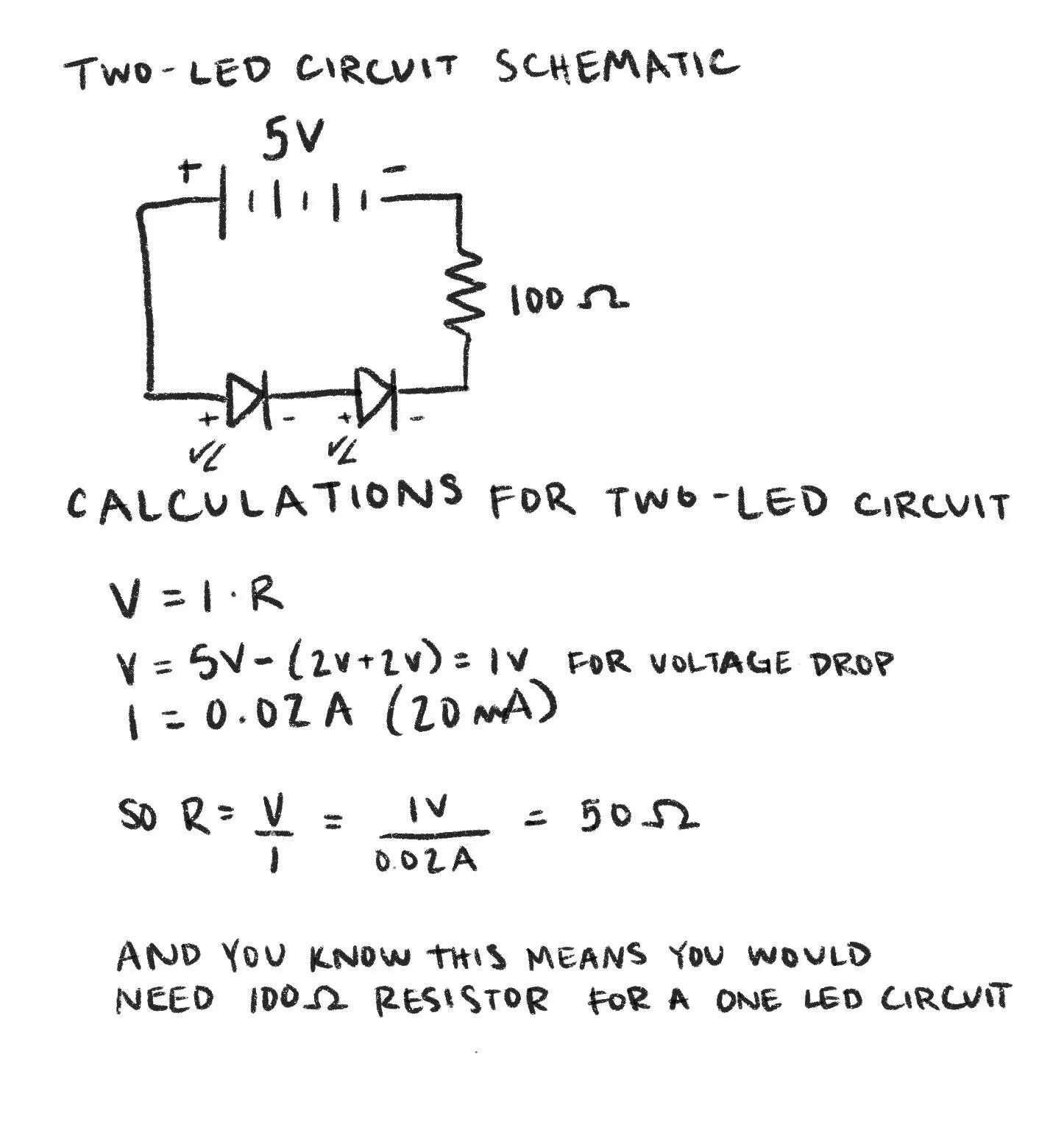
Calculation and schematic for two-LED circuit

Calculation and schematic for two-LED circuit

To begin, I have calculated the amount of current running through our basic LED circuit from the last lab if I replace the resistor with one that is 10k Ohm.

If I add a second LED to the series circuit, I now need to calculate a new value required for the resistor to maintain a 20 mA current across both. Pictured to the left is this calculation and schematic, and below is a photo of the circuit itself.

Series circuit with two LEDs, the first being slightly brighter than the second

Series circuit with two LEDs, the first being slightly brighter than the second

Next, I added a third LED to this series. In the picture, although hard to tell, you can see that the second LED is far dimmer than the first, and the third does not light up at all. This is because our LEDs have a voltage drop of 2V, and since we are using only 5V, this does not leave enough voltage in this circuit to power the third LED.

Series circuit with three LEDs, the first being brighter, and the third not lighting up at all.

Series circuit with three LEDs, the first being brighter, and the third not lighting up at all.

Parallel circuit with three LEDs, which are not powered on in this photo

Parallel circuit with three LEDs, which are not powered on in this photo

I then rearranged my circuit into a parallel circuit with the three LEDs. I used 100 Ohm resistors for each LED, but I realized after photographing this that I could use a much higher Ohm resistor. I did not attach the photo of this circuit when on, because the LEDs were so bright that it made the coloring difficult to see in a photo.

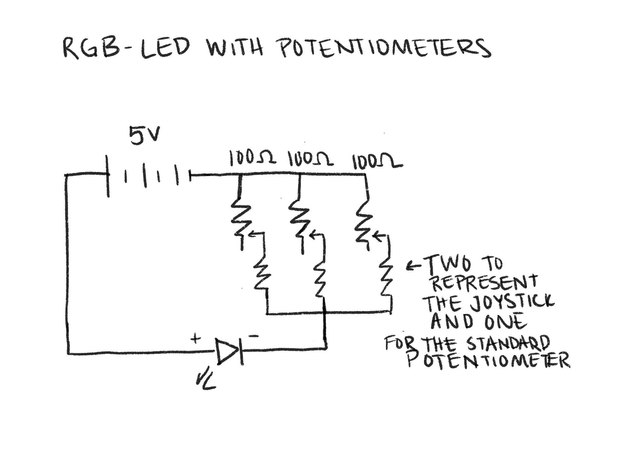
Next, I changed out all three of the LEDs with an RGB-LED, and attached a joystick and potentiometer. The joystick will control two of the colors while the potentiometer will control the third. This is where I ran into some problems. For some reason, the joystick was successfully controlling the red and green LED, but the blue was not turned on, and twisting the potentiometer was fruitless.

RGB-LED with only the green and red LED functioning using the potentiometer

RGB-LED with only the green and red LED functioning using the potentiometer

RGB-LED working partially with the potentiometer after holding the jumper cables in particular spots

RGB-LED working partially with the potentiometer after holding the jumper cables in particular spots

I had to do a lot of trouble-shooting, expecting that I was simply doing something wrong, but I came to the conclusion that the potentiometer was not working properly. When I fiddled with the jumper wires, it would somewhat bring the blue LED on, but it was inconsistent. I then switched out the potentiometer for a regular old jumper cable, and BAM! It worked!

Schematic for RGB-LED circuit with potentiometers

Schematic for RGB-LED circuit with potentiometers

Resistors in Series

Schematic and calculations for a circuit in series

Schematic and calculations for a circuit in series

To confirm these calculations, I modeled the circuit in PhET. These were confirmed by checking the voltage of the second resistor, which matches that of my second voltage drop calculation.

Now moving on, I have calculated the overall resistance, overall current, and voltage drop across resistors of the given series example.

A PhET model of a circuit with three resistors and 5V, measuring the voltage at the second resistor

A PhET model of a circuit with three resistors and 5V, measuring the voltage at the second resistor

Resistors in Parallel

Schematics and calculations for a circuit in parallel

Schematics and calculations for a circuit in parallel

I confirmed these calculations in PhET once again. You can see that my calculation for V2 matched the voltage on the PhET circuit.

I then did the same with two more parallel circuits, which have different characteristics from series circuits.

A PhET model of a parallel circuit with three resistors and 5V, measuring the voltage at the second resistor

A PhET model of a parallel circuit with three resistors and 5V, measuring the voltage at the second resistor

Arduino Installation

Lastly, I prepared for next week by setting up and installing the Arduino environment. That info is pictured below.

Screen Shot 2021-02-02 at 9.15.17 PM.png

Basic Electronics

In this week’s lab, we are dipping our toes in the water of basic electronics and circuits by creating an LED circuit

Breadboard with only the jumper wire and and voltage regulating circuit connected

Breadboard with only the jumper wire and and voltage regulating circuit connected

To begin, I have connected my breadboard voltage regulating circuit board and set the jumpers to 5V, as well as connecting to a 9V battery. On the positive side, I have connected a jumper wire, then added my LED, followed by a 220 Ohm resistor to the negative side. I chose to lay this circuit out on my breadboard from left to right so as to make it easy to understand and easy to follow the schematic.

LED light powered on with 220 Ohm resistor

LED light powered on with 220 Ohm resistor

The second picture, to the right, is using a 1K Ohm resistor, which limits the voltage to the LED and therefore make the light dimmer. Although slight, the change is existent.

Full circuit made with jumper wires connecting to LED and then a 220 Ohm resistor

Full circuit made with jumper wires connecting to LED and then a 220 Ohm resistor

When the switch is turned on, the LED lights up. The first picture, on the left, is the light emitted with the 220 Ohm resistor.

LED light powered on with 1K Ohm resistor

LED light powered on with 1K Ohm resistor

Circuit with a light-dependent resistor rather than a fixed resistor

Circuit with a light-dependent resistor rather than a fixed resistor

After working with the fixed resistors, I swapped them for a light-dependent resistor (LDR), which is pictured above. This time, when switched on, you can see in the photo to the right the amount of light emitted by the LED when there is significant overhead light shining on the LDR.

LED light powered on with the LDR covered

LED light powered on with the LDR covered

LED light powered on with the LDR uncovered

LED light powered on with the LDR uncovered

I then adjusted the light to the LDR by covering it with my finger, and as pictured to the left, the LED was noticeably more dim.

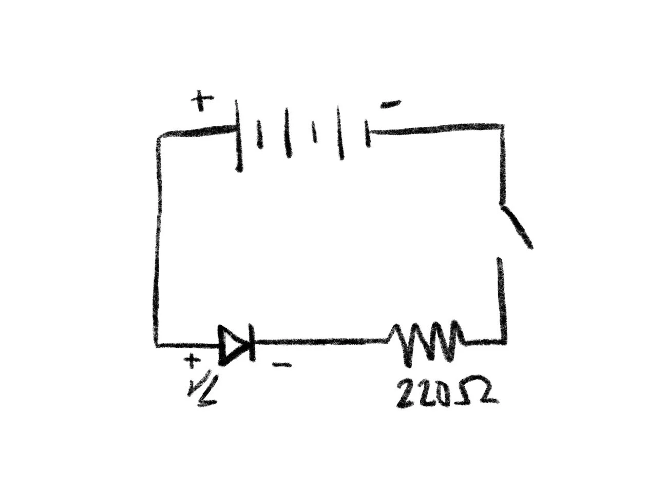
Schematic of basic LED circuit with a 220 Ohm resistor

Schematic of basic LED circuit with a 220 Ohm resistor

Lastly, the schematic for the basic LED circuit is pictured above. This depicts the power source at the top, with the positive side going to the LED, then the 220 Ohm resistor and switch to show the ability to open and close the circuit, or turn the light on and off with a button.